-
×
 Đồng hồ đo volt + ampe 10A-100VDC
1 × 100.000VND
Đồng hồ đo volt + ampe 10A-100VDC
1 × 100.000VND
Tổng số phụ: 100.000VND
Hi , Guys
I have UHF FM Transmitter with power about 5W
I want it to send video signal through AM the carrier frequency
here the important section of schematic :
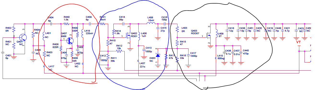
I tried to inject signal in Q407 emitter ( i think this make low level AM ) after remove R408 the picture shows up in my TV with lot of noise and no luck with range .
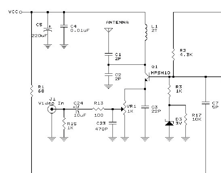
Then I tried same thing with another VHF Transmitter ( thinks modifying in low frequency easier and lower the interference is it right ) and here is the VHF one :
the point i inject the signal is Q3 emiter

The picture show up in tv with good range about 300M ? with dipole antenna both TX RX .
this is my way to inject signal :
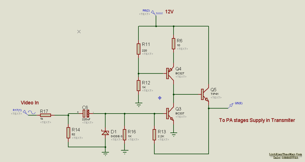
is this Method below better ? ( it is done in RF power amp stage Not like i’m doing IN per amp or buffer stage ? )

the Transmitter’s I have is have PPL and VCO to control and stabilize the carrier frequency
thanks a lot
Your third picture is nearest to the way to do it but you have to inject more the VCC of video for it to work properly. The issue is the output stages shown are designed to produce maximum output power but for AM you only want that at the peaks of the video waveform. You have to ‘back off’ the power to around 50% so the video waveform can both decrease and increase the envelope. If you don’t do that, the video waveform becomes highly compressed which results in very poor contrast or more likely, picture that refuses to lock properly, rolling and tearing all the time.
Also note that if you are feeding video along a normal cable to the input, it should be terminated with 75 Ohms resistive load.
This link might help: http://www.atv-projects.com/AM_Modulator.html
Brian.
Years ago I built something similar with schematic nr. 4, and the circuit works just fine.
…which is almost identical in circuit and operation to the link I posted, both modulate the PA stage current.
Worth noting that in many PA stages there is a fairly large capacitor across the supply. It has to be removed or changed to a much lower value or it will shunt the modulation.
Brian.
Thanks for the replys .
In the link brain sent the writer change PA stage Current to match Video signal after amplify it . this similar to schematic nr. 4 .
but writer said also signal can feed in the driver stage ! that what i’m confused about ?
and also brain u main modulation index if it increase too much the picture look badly are u mean the modulation index by your words ?
mr. vfone
what the range of your transmiter was ?
and what the antenna ?
The original circuits are FM, that means the output stage runs at full power 100% of the time. Because the amplifiers run at full power, there is no need for them to be linear. For AM you have to vary the power, thats why its called Amplitude Modulation. If you try to modulate a driver stage there is no guarantee there will be a linear relationship between the video level and the RF level because later stages are not biased to allow that.
The modulator circuits in the PA work by restricting the output power to ~50% then using the video signal to adjust it down towards zero and up towards maximum. It may still not be linear but it will be much nearer than modulating driver stages. You have to keep below 100% modulation so there is some residual RF to carry the sound signal if there is one.
Modulation index is nothing to do with it, linearity is the problem. The term modulation index refers to how much the frequency changes for a given amount of modulating signal so it only applies to FM. In this case, the problem is the video signal gets ‘crushed’ either at the top of the waveform or at it’s bottom, that either causes severe contrast errors (for example only the brightest parts of the picture showing against a black background) or loss of the sync pulses which lock the monitor to the video, that makes it tear or roll.
Brian.
if you intention is just to send video signal to a distance, I suggest you to use a Video Modulator IC with a boosted RF signal.The discrete solution will absolutely troublesome because clamping,modulation depth,sound carrier accuracy,group delay during transmission etc. will all be trouble.
But if you would learn something, go ahead.
At that time (about a quarter of century ago I used BLX65 (2W) for the driver and BLX68 (7W) for the final stage.
From a hilltop location using a 9 elements Yagi antenna, the longest distance my signals were received was about 50km.
I used this :
First I connect it to driver Stage ( or pre amp stage I dont know exactly ) the picture comes
very fine and stable on TV but no colors ( I think the reason is the video amp i use invert the
signal ? ) and the range too bad even the transmitter current is low .
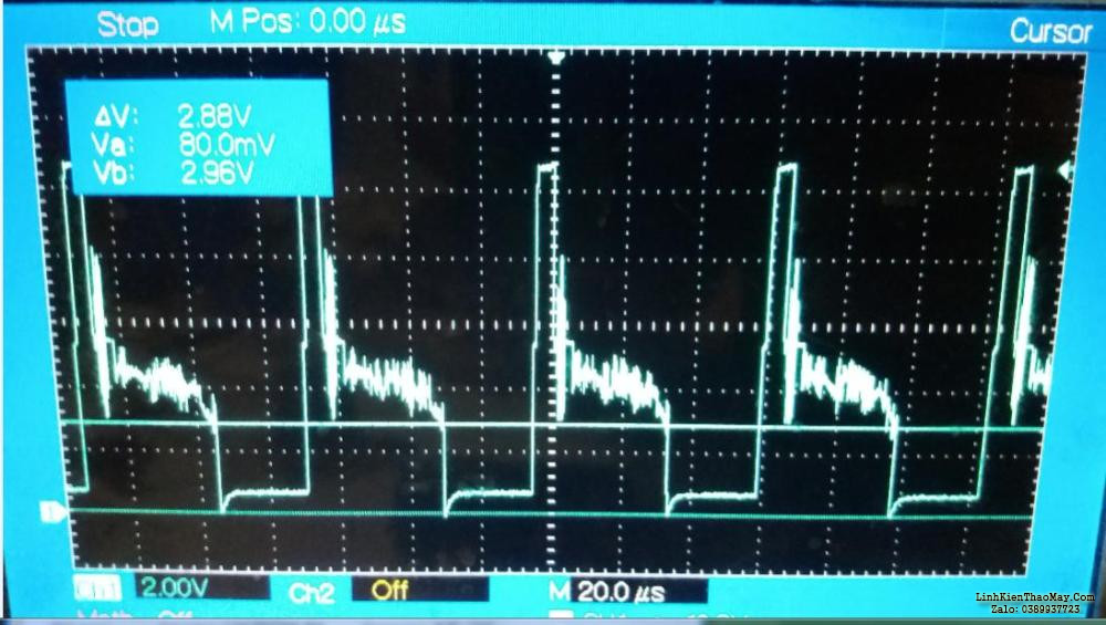
here is my modulator Out with 100R load ( it divided the signal by 3 or 4 times ) :
then I disconnect the PA stages form its supply ( it is draw about 2.5A ) and give it supply
from my modulator ( I dont know what max current it can supply ? ) .
When i connect the modulator out to PA stage supply the signal drop to almost no thing and the
final modulator transistor gets too hot ?
p.s : The Supply of PA stage is 8.5 V and current is 2.5A .
pls help
and thanks a lot .
I think The problem is TIP41 maybe it is not biased correctly cuz i replace the original transistor mje180 with it .
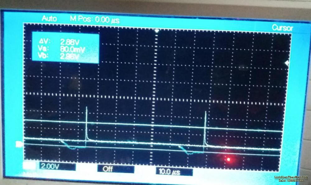
when no video the out of modulator is 3V constant , when feed it in PA stages drop to 1V.
is the tip41 cant handle frequency of video signal ?
and what frequncy should i use in simulation rather than video signal ?
TIP41 has an FT of 3MHz although in this configuration that might work. The frequency response for normal TV and sound should ideally be flat up to about 8MHz so for simulation that would be a good figure to use.
The quiescent power dissipation should be about 6 times the PA current while the PA has 6V supply, that is likely to be several Watts so expect it to run hot, it will need a heat sink!
You really don’t want R17 in the circuit, it seriously drops the video level and assuming good practice of using screened video cable, will cause a serious impedance mis-match. I would wire R14 across the track of a 100 Ohm potentiometer, feed video in at the top and connect C6 to the wiper (and reversed polarity!). The control will then set the modulation depth. Note that if you are also transmitting sound, you must reduce the modulation level so there is always some residual carrier being sent.
I’m not sure what D1 is supposed to do. In similar circuits it is used for DC restoration but that wont work in the configuation shown.
Brian.
best regards
I make it work with this modulator :
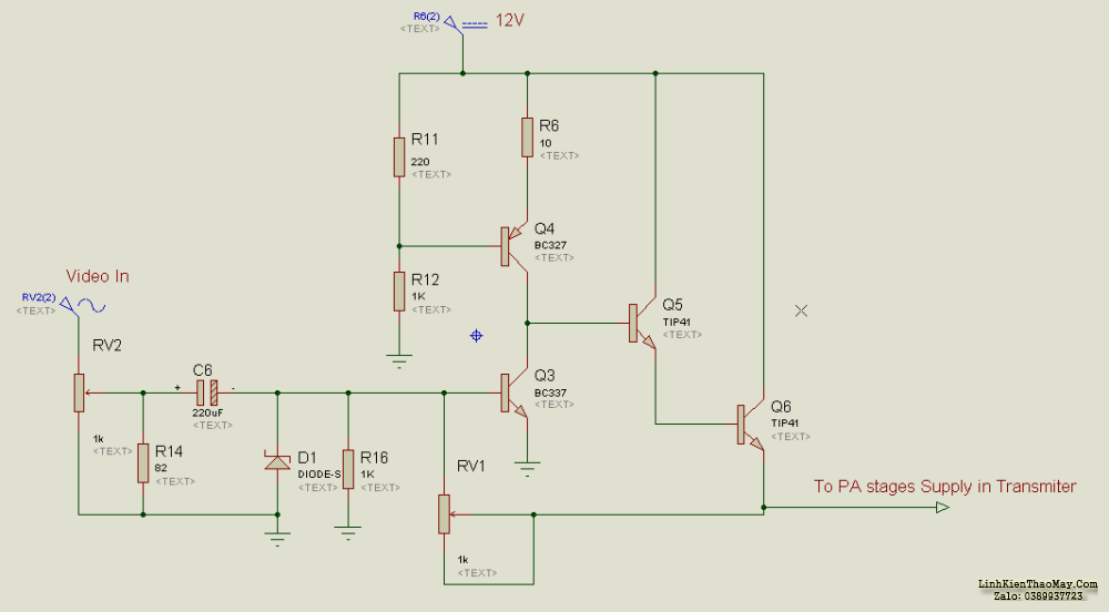
I use RV1 to adjust offset of the signal and RV2 to adjust the modulation depth ( I think ? )
The picture show very fine with colors on TV ( the colors problem solved by TV settings )
the default supply volt of PA stages is 8.5V and the device shut off at 6 v should I make the modulation depth from 6V to 8.5V ?
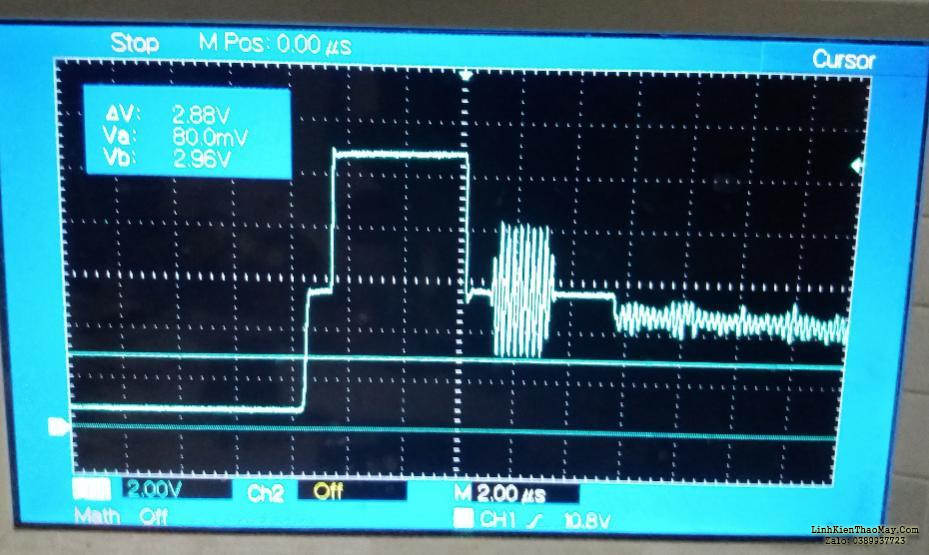
and the pireod signal stay on 8.5V ( I mean PA supply) is very short which make the carrier signal time at full power very short either :

here is sample :
after short time the transmitter PA 90% dead dont know why ?
RV1 is to set the quiescent (no modulation) PA current. RV2 sets the modulation depth.
I meant to change RV2 to 100 Ohms value and connect R14 across it’s track (video input to ground) because the standard for analog video cables is a 75 Ohm termination. The 100 Ohm potentiometer and 82 Ohms will give about 45 Ohms. If you rewire it and change R14 to 270 Ohms it will present 73 Ohms load which is better.
You can adjust both controls by watching the picture, feed it a steady video signal, ideally color bars and gradually increase R2. When it starts to tear/roll or the difference between lightest or darkest bars starts to reduce, adjust RV1 to try to correct it. when you have found the best position for RV1, reduce RV2 to drop the contrast to a more reasonable level. What you are trying to achieve is the PA current that allows maximum amplitude before the top or bottom of the waveform become distorted.
Where are you monitoring those video waveforms? The best way to adjust it is to use oscilloscope inputs, one on the video source (at the input of the circuit) and one on a diode probe across the RF load (antenna socket, across a dummy load or antenna). If you set the scope to XY mode it should draw a diagonal line or at least a steady diagonal shape. RV2 should set the length of the line and RV1 should set how straight it is. If RV1 is set wrongly, the top or bottom of the line will go flat, you adjust the controls to get the longest straight line possible.
If the PA seems to go dead, the most likely reason is lack of current, do you have a heat sink on Q6?
Brian.
I cant set my oscilloscope across antenna or RF load cuz its frequency 100MHZ and I’m working with UHF .
yes Q6 have a big heat sink .
I think tip41 cant handle sync pulse cuz it dont appear sometimes in the signal .
are TV reception distorted when it near a 5W or 7W UHF transmitter about 5 meters ?
The video waveform which I fed it to PA supply have max Amplitude of 4.5V ( I think it should be 7 or 8 V cuz default 8V ) when I raised it up the picture distorted and cant fix it with potentiometers ever ?
I think PA at 4.5V rather than 8 dont output so much power ? ( is it 50% of power ? )
sorry for Voracity of science
best regards
michle
I did write “and one on a diode probe across the RF load (antenna socket, across a dummy load or antenna)”, you seem to have missed the bit about the diode probe!
The probe rectifies the RF, regardless of the frequency and recovers it’s envelope, in other words the amplitude of the signal. If everything works properly, the relationship between video and RF amplitude should be linear so the X and Y deflection of their signals on the scope should show a straight line. If the line flattens at one end or the other it means the PA stage has hit zero or maximum power, in other words it can’t follow the video waveform. The bias control VR1 should be set so the ‘flat’ is symetrical and VR2 adjusted to keep the line short enough that it doesn’t reach the flat region.
TIP41 is not the best choice of power transistor and using two of them in series makes things even worse, the first one carries far less current and may be changed to a smaller one with better high frequency parameters. The circuit I linked to earlier has been used to send color AM from a transmitter running at 435MHz over distances of more than 30Km so the modulation principle does work. Don’t expect miracles though, remember you are trying to modify a stage optimized for FM to carry AM instead.
Brian.

I have succeeded by injected the amplified video signal in the last PA transistor after disconnect its supply line , I adjust the pots by watch the carrir wave in scope ( it had 50 Vp-p = 6.3 W ) with RF probe dummy load and the picture in TV .
many thanks for helpful betwixt.
I will test the real range after I get a license , with my homemade yagi .
which is best Omnidirectional antenna for this ?
Well done.
It is easier after the first time! I have been doing this kind of thing for 50 years!
The best omni-directional antenna depends on the frequency but I’m guessing you are using ~435MHz so a vertical antenna on a ground plane will probably work best. For directional use, a Yagi is best.
Brian.